Technical
Throttle valve Synchronization.
In order to achieve peak performance and efficiency, each cylinder must produce the same amount of power. To do so, the vacuum in the intake manifold to each cylinder must be the same i.e. 'balanced' or 'synchronized'.
Our SynchroKing devices directly measure the the vacuum in each manifold and display the value on the digital display. Any unconnected channels are ignored by the device, showing ' - - - ' on the display.
'mmHg' stands for millimeters of Mercury, a commonly used unit for vacuum and carried over from a traditional Mercury vacuum column.

Figure 1 - SynchroKing 2 measuring 28mm Hg on channel 1, zero on channel 2
In addition, the device instantly compares the vacuum levels between the active channels and displays the differnetial in the bar graphs right above the numerical displays. Each bar represents a 20mmHg differential. It is important to note that the bar displays do not represent the measurement, rather they show the comparison between measurements. (So no, you will not ever run out of range on the bar displays.)
Find a desktop demonstration of the SynchroKing 2 on youtube:
Figure 2 below shows a SynchroKing 2 measuring 154mmHg on channel 1 and 78mmHg on channel 2. The bar displays indicate a differential vacuum of between 60 and 80 mm from average.

Figure 2 - SynchroKing 2 measuring 154mm Hg on channel 1, 78mmHg on channel 2
When the measurement of an individual channel is within 20mmHg, the two center LEDs on the bar displays will be illuminated, indicating that the channel is practically synchronized. Figure 3 shows LambdaKing 4 with 3 channels measuring various vacuum levels.

Figure 3 - SynchroKing 4: Channel 1 disconnected. Channel 3 within 20mmHg from the average.
Our SynchroKings come with a detailed user manual with various examples of readouts.
Because the vacuum rapidly fluctuates in the intake manifolds with the engine running, it is necessary to dampen the measurements, otherwise the readout would become a useless blur. Each SynchroKing is equipped with a dampening knob that enables the user to select the the appropriate level of dampening. The dampening function can be thought of as the equivalent of a bung of choke valve in a conventional gauge. The dampening should be set such that a usable compromise between responsiveness and readability is achieved.
Below are a few examples of SynchroKings used with various engine configurations.

Setup Example 1 - SynchroKing 2 on V-twin with two carburettors

Setup Example 2 - SynchroKing 4 on In-Line 4

Setup Example 3 - SynchroKing 2 on a V8 with two inlet manifolds
Air Fuel Ratio
It takes 14.7kg of air to fully combust 1 kg of petrol. This 14.7:1 ration is referred to as the stoiciometric Air to Fuel Ratio (AFR). The vehicle's fuel system should be set up such that the engine is supplied with the correct amount of fuel to suit the operating conditions.
Generally a lower Air to Fuel Ration ('rich mixture') is desired when seeking peak performance, whereas a higher AFR ('low mixture') results in better fuel economy.
Lambda is a commonly used a unit of measure for Air/Fuel ratio. Lambda is defined as Lambda=AFR/14.7. For example, if the AFR=13.2, then Lambda 13.2/14.7=0.9.
The table below shows a range of AFR/Lambda figures.
Table 1 AFR-Lambda
Our LambdaKing devices enables the AFR to be determined by measuring the oxygen content in the exhaust gas, exactly as the oxygen sensor in fuel injected vehicles does. The numerical display shows the AFR or Lambda value; the user can switch between AFR and Lambda as desire by pressing the sel button.
The bar display gives a graphical display of the air to fuel ratio (AFR). Range: 9-19 / Lambda 0.61- 1.29. Figure 4 below show a LambdaKing 1 indicating a Lambda value of 1.22.

Figure 4 - LambdaKing 1
The LambaKing devices comes supplied with a wideband Oxygen sensor that can be installed into an existing socket of the vehicle's exhaust. If no free socket is available then the included socket can be installed in the desired position on the exhaust. A detailed instruction on how to install the socket is included in the device manual.

Figure 5 - Wideband sensor, plug and socket
The pictures below show various setups for measuring the exhaust from individual cylinders or from the combined exhaust stream.

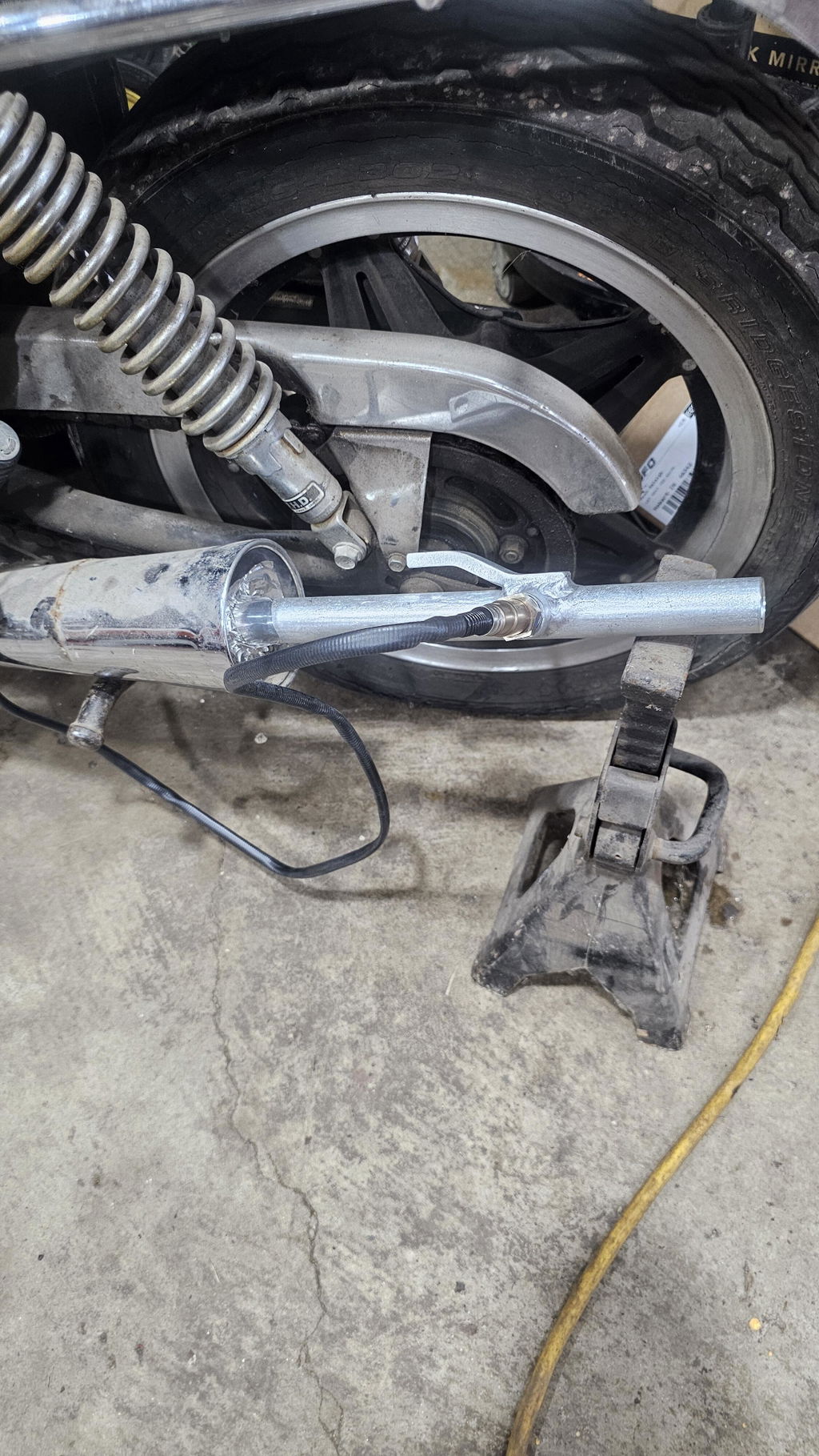
Figure 6 - LambdaKing 1 measuring from the rear cylinder on a V twin.

Figure 7 - LambdaKing 1 measuring from the front cylinder on a V twin.

Figure 8 - LambdaKing 1 measuring the combined exhaust flow from a V twin